
User`s guide

Scanner Maintenance and Calibration 8
Agilent 5500 SPM User’s Guide 141
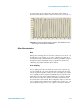
by an equal and opposite field in the other direction. The effect of
hysteresis is that the trace will be offset from the retrace, as in Figure 92.
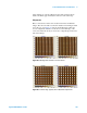
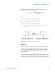
Figure 92 Scanner hysteresis before correction. The yellow line is the
Trace image, and the blue is the Retrace.
Other Characteristics
Bow
During raster scanning, the free end of the scanner moves in an arc over
the full range of the scanner, as opposed to a flat line in a plane above
the sample. Bowing is minimized by the “balanced pendulum” design of
the Agilent scanners. Residual bowing is typically accounted for by
“flattening” algorithms in the PicoView software.
Cross Coupling
Cross coupling is the effect in which movement of the scanner along
one axis (usually X or Y) causes unwanted movement along the other
axis (Z). Systems using tube scanners are more susceptible to geometric
cross coupling because a single four-quadrant tube provides motion in
all the three axes. The larger Agilent multi-purpose scanners, with 90
micron X/Y scan range, use separate piezoelectric elements for X/Y
movement and for Z movement. This configuration helps to reduce the
cross coupling between different axes. Smaller range scanners (e.g., 10
micron X/Y scan range) use two sets of plates (one each for X and Y