
User`s guide

Scanner Maintenance and Calibration 8
Agilent 5500 SPM User’s Guide 148
the slow scanning axis so the range will be reduced as a time
consideration.
Only one Topography image is required for Y calibration. The other
image can be assigned to display flattened Topography data.
Y Non-Linearity
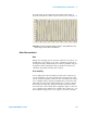
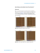
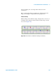
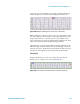
Obtain an image of the calibration target. Using the Cross-section tool,
set markers at the uppermost and bottommost feature along a vertical
cross section (Figure 101).
Figure 101 Cross-section in Y direction showing non-linearity