
User`s guide
Scanner Maintenance and Calibration 8
Agilent 5500 SPM User’s Guide 152
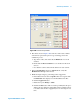
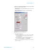
top and the bottom of the data plot is flat before making the
measurement.
If the step size is not within 5 % of the actual value, calculate a new Z
sensitivity term using the following equation:
After the X, Y and Z calibration steps have been completed, the scanner
is fully calibrated. The remainder of this procedure will help to create
and finalize the required calibration software files.
Servo Gain Multiplier
If you were to image a standard sample and view the topography or
error signal on an oscilloscope while increasing the gains, you would
see that, up to a point, the signal would be relatively smooth as the
system accurately tracked the sample surface. At some gain level,
however, the oscilloscope image will begin to display small, high
frequency oscillations. This is similar to feedback in a microphone, with
the gains so high that each oscillation is multiplied and fed back into the
signal.
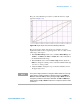
The Servo Gain Multiplier is a factor that sets the point at which this
“feedback” will occur for a typical signal. Following a successful X, Y
and Z calibration, the Servo Gain Multiplier must be set for each
individual scanner. Enter the value in the Scanner Setup window.
Experimentally it has been shown that an integral gain setting between
15 and 20 works well for most scanners.
Archive the Calibration Files
Copy the newly created calibration files to a disk for archive. Label the
file with the scanner model, serial number and calibration date.
NewSensitivity
CurrentSensitivity Kno wnSize
MeasuredSize
-------------------------------------------------------------------------------------
=