
User`s guide

Closed-Loop Scanners 9
Agilent 5500 SPM User’s Guide 155
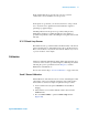
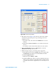
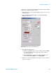
Figure 106 Scanner Setup window
4 The values shown in Figure 106 for the X, Y and Z Sensor Offset
and Gain are typical and represent a good starting point for the
calibration process.
a Type in the values, and ensure that the Enabled boxes are all
checked.
b Ensure that the Reversed Gain boxes are checked for X and Z
Sensors.
c Note that the scanner values will be different for each scanner.
5 In the Scan and Motor window’s Advanced tab, verify that
Enabled Closed Loop is not selected.
6 Enable the high voltage by performing a false engagement:
a In the Servo window enter a Setpoint value more negative than
the Deflection value displayed on the Head Electronics Box.
b Click the Approach button.
c Reduce the Z piezo Range to 0.000.
d Click the Center button. This avoids the possibility that the piezo
will become depolarized by being fully retracted (which is where
it would be after the false engagement) for an extended period of
time.