
User`s guide
MAC Mode 10
Agilent 5500 SPM User’s Guide 164
3
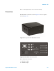
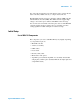
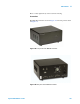
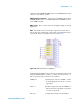
Input summed to AAC drive signal.
4 Deflection output from detector.
5 Amplitude output from lock-in amplifier.
6 Phase shift signal from lock-in amplifier.
7 To Serial Port on computer.
8 Aux output for custom applications.
9 44-pin cable from AFM Controller.
10 44-pin cable to Head Electronics Box.
11 25-pin cable (if applicable).
12 25-pin cable to HEB (if applicable).
In addition to the standard cabling for your microscope, the following
connections must be made to use the MAC Mode in your system (a
complete wiring diagram is included in Appendix A).
Power Cord Connect the power cord from the back of the MAC Mode
controller to building power. Do not power on the controller at this time.
Computer Connection Connect the RS-232 serial cable from the
SERIAL port on the MAC Mode controller to a COM port on your
computer. The port number will be automatically detected if your
computer has more than one COM port.
Head Electronics Box Connection Connect the short DB44 cable
from the MAC Mode Controller to the CONTROLLER connector on
the Head Electronics box (HEB). Use a DB44 cable between the
MICROSCOPE connector on the HEB and the 44-pin connector on the
microscope.
AFM Controller Connection Connect a DB44 cable from the MAC
Mode controller to the PicoSPM II connector on the AFM Controller.
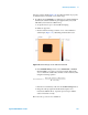
Sample Plate Connection Plug the round jack of the EC/MAC cable
into the underside of the microscope stand, and the 6-pin connector into
the MAC sample plate. When using Acoustic AC Mode, this connection
is not necessary.
Hardware and Sample Setup
Most hardware and sample setup options with MAC Mode are identical
to those for standard AAC and MAC Mode operation, as covered in