
User`s guide

MAC III Mode 11
Agilent 5500 SPM User’s Guide 170
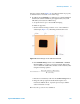
cable between the MICROSCOPE connector on the HEB and the 44-pin
connector on the microscope base.
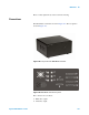
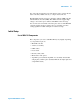
AFM Controller Connection Connect the longer DB44 cable from the
CONTROLLER connector on the MAC III to the PicoSPM II connector
on the AFM Controller.
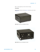
BNC 1 and 2 These connectors are user configured outputs for custom
applications.
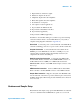
AUX The AUX connector has the drive output from each lock-in, a
drive-in that can be summed into each lock-in, and an auxiliary input to
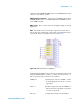
each lock-in. The pin-out diagram is shown in Figure 116:
In this diagram the numbers refer to the slots in which the lock-in cards
sit inside the MAC III box. Lock-ins 1, 2 and 3 are located in slots 1, 3
and 5, respectively. The connections are as follows:
AUXIN 1-5 AUX inputs for each slot. AUXIN 1, 3 and 5
are the AUX inputs for Lock-ins 1, 2 and 3,
respectively.
Drive 1-5 The drive outputs from each slot. DRIVE 1, 3
and 5 are the Drive Out signals for Lock-ins
1, 2 and 3, respectively.
Drive_In A single drive line that can optionally be
Figure 116 AUX Connector pin-out diagram