
User`s guide
MAC III Mode 11
Agilent 5500 SPM User’s Guide 179
10 V, beyond which the signal will be clipped. The
default value is x1 (the amplitude times 1).
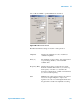
Zero Phase Sets the phase at the current frequency to zero,
making it easier to interpret phase changes from the
current value.
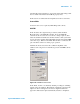
Q Control On By applying a phase-shifted version of the
cantilever drive signal on top of the drive signal, Q
control can either increase or decrease the effective
quality factor of the system. Select this box to
enable the Q Control feedback loop. By default, Q
Control is turned Off.
Drive (%) Sets the amplitude of the Q Control phase-shifted
signal, stated as a percentage (0-100 %) of the
maximum available.
Optimize Sets the optimal Q-Control Phase Shift and Drive.
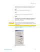
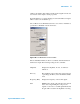
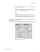
The EFM tab shows the parameters for Lock-in 2. Drive, Frequency and
Gain settings have the same functions as described for Lock-in 1 above.
As mentioned, Lock-in 2 is used as the source for the AC tip bias. You
will typically need to sweep the frequency of Lock-in 2 to ensure that
the electrical response of the cantilever does not interfere with the
mechanical response provided by Lock-in 1 and to see if there are any
other resonances present. To do so, select the EFM Tune check box,
then choose Manual Tune in the AC Mode Tune window. Determining
the best frequency for your sample and tip will require some iteration.
Two rules typically apply:
• The frequency should not be an integral factor of the Lock-in 1
frequency.
• The frequency should not be close (within 10-20 kHz) to the
Lock-in 1 frequency.