
User`s guide
MAC III Mode 11
Agilent 5500 SPM User’s Guide 181
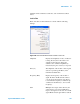
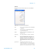
The Main tab shows settings for Lock-in 1 and Q-Control:
Amplitude Displays the amplitude, in volts, of cantilever
oscillation amplitude.
Drive (%) The amplitude of the Lock-in 1 drive signal,
stated as a percentage (0-100 %) of the
maximum available 10 V.
Frequency (kHz) Displays the frequency of the Lock-in 1 signal.
From the AC Mode Tune window you can
sweep the frequency of Lock-in 1, to determine
the frequency at which the tip oscillation is
maximized (i.e., the resonant frequency).
Gain Multiplies the output of the lock-in by the
selected factor. Use a larger multiplier to
improve the signal-to-noise ratio for a small
signal. Ensure that the gain will not result in an
amplitude exceeding 10 V, beyond which the
signal will be clipped. The default value is x1
(the amplitude times 1).
Zero Phase Sets the phase at the current frequency to zero,
making it easier to interpret phase changes from
the current value.
Q Control On By applying a phase-shifted version of the
cantilever drive signal on top of the drive signal,
Q control can either increase or decrease the
effective quality factor of the system. Select this
box to enable the Q Control feedback loop. By
default, Q Control is turned Off.
Drive (%) Sets the amplitude of the Q Control phase-shifted
signal, stated as a percentage (0-100 %) of the
maximum available.
Optimize Sets the optimal Q-Control Phase Shift and
Drive.
The KFM tab shows the parameters for Lock-in 2. Drive, Frequency and
Gain settings have the same functions as described for Lock-in 1 above.
As mentioned, Lock-in 2 is used as the source for the AC tip bias. You
will typically need to sweep the frequency of Lock-in 2 to ensure that
the electrical response of the cantilever does not interfere with the