
User`s guide
MAC III Mode 11
Agilent 5500 SPM User’s Guide 182
mechanical response provided by Lock-in 1 and to see if there are any
other resonances present.
To do so, select the KFM Tune check box, then choose Manual Tune in
the AC Mode Tune window. Determining the best frequency for your
sample and tip will require some iteration. Two rules typically apply:
• The frequency should not be an integral factor of the Lock-in 1
frequency.
• The frequency should not be close (within 10-20 kHz) to the
Lock-in 1 frequency.
Optimize Phase shifts the phase signal to maximize the X Component 2
(i.e., to maximize contrast).
The output from the servo is routed to the SP Channel and to the Drive
Offset of Lock-in 2. To map the output (which is the KFM signal),
choose SP in the Realtime Images window.
I Gain and P Gain are the Integral and Proportional Gains for the MAC
III internal servo loop. Set the I and P Gains to obtain the sharpest image
in the Realtime Images window.
X Component 2 and Phase 2 are routed to the Aux 1 and Aux 2 outputs,
respectively, for monitoring. To view changes in the EFM signal,
choose Aux 1 in the Realtime Images window.
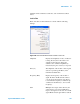
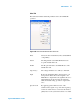
Advanced Software Control Options
The Advanced AC Mode property sheet gives you more signal routing
and control options than the simplified options described above. To
view the AC Mode settings click Controls > Advanced >AC Mode. The