
User`s guide
MAC III Mode 11
Agilent 5500 SPM User’s Guide 184
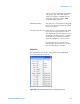
an amplitude exceeding 10 V, beyond which
the signal will be clipped. The default value
is x1 (the amplitude times 1).
Bandwidth How far to either side of the selected
Frequency the lock-in circuitry is able to
process information. Bandwidth can range
from 40 Hz to 20 kHz. The default
“Automatic” setting will adjust the
bandwidth based on the Input signal.
Input The source signal that is routed to the input
of the lock-in. Choosing Aux will route the
signal from the MAC III controller’s AUX
connector to the lock-in input. The default
Input is the cantilever Deflection.
Phase Offset Applies an offset to the calculated phase
signal. The value, stated in degrees, is 0 by
default; however, it can be adjusted such
that the calculated phase will read 0, making
it easier to interpret changes in phase. The
Auto Tune function (Controls > AC Mode
Tune) will automatically set this offset
value.
Lock-In Harmonic Setting this value will drive the reference
signals at a fraction or multiple of the drive
signal. This value allows you to examine the
signal at harmonics of the drive signal. The
default value is 1.
Drive Offset Applies an offset, in volts, to the drive
signal. The default value is 0.
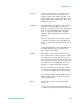
Select the From Servo check box to add the
output from the MAC III internal servo loop
to the drive signal. This option is used in
KFM Mode, in which the servo acts to
maintain a DC Tip Bias that counteracts any
electrostatic field on the sample. The servo
output, therefore, will change as the sample
charge changes; this value is also fed to the
SP channel for imaging.
Phase Shift (°) Each lock-in includes two, orthogonal
reference signals. This parameter will shift
the phase of the reference signals with