
User`s guide
Introduction to the Agilent 5500 1
Agilent 5500 SPM User’s Guide 19
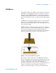
collection of data points is then synthesized into the “SPM image,” a
3-dimensional map of the surface characteristic being examined.
The most common SPM images are topography images, in which the
third dimension, Z, for any given X/Y coordinates, is the relative height
of the sample surface. This interpretation implies that the sharp probe
does not deform the sample surface—the harder the sample surface, the
more accurate is this interpretation. In other words, the tip follows the
height variations of hard surface with higher fidelity than it does soft
surfaces.
Topography measurements are in general calibrated against height
standards.Therefore, topography images may be compared for
quantitative information, provided the systems have been correctly
calibrated and operated, and that the data is properly interpreted.
In other types of SPM images, the third dimension is a measure of the
relative strength of a detectable interaction between the probe and
sample. The image is usually recorded simultaneously with, and
displayed along side, the topography image of the same sample area.
This helps reveal any correlation between topography and the
interaction.
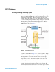
In some instances, the signal from the SPM’s detector is mapped
directly; for example, the deflection of the probe cantilever, or the
current through a metal tip. In other instances, the signal from the
detector serves as the input of a feedback system which attempts to
maintain the detector signal at a user-defined setpoint. The output of the
feedback system can then be mapped to construct the image.
SPM can also be used for “non-imaging techniques,” or
“nano-manipulation,” in which the probe is used to modify the sample
surface. For example, one can use the probe or tip to rearrange
nanometer-scale objects physisorbed on that surface. Essentially, the tip
serves as a nano-scale finger to interact with the sample.
Nano-manipulation is sometimes performed in the plane of the sample
surface (in-plane) and sometimes at right angles to this plane
(out-of-plane nano-manipulation). An example of out-of-plane
nano-manipulation is attaching the probe tip to the end of a
macromolecule on the sample surface, and pulling the molecule so that
its secondary or tertiary structure unfolds. This is now an extremely
active area of research, with applications extending to fields as diverse
as drug discovery and composite materials design.