
User`s guide

Introduction to the Agilent 5500 1
Agilent 5500 SPM User’s Guide 20
SPM Techniques
Scanning Tunneling Microscopy (STM)
The earliest, widely-adopted SPM technique was Scanning Tunneling
Microscopy (STM). In STM, a bias voltage is applied between a sharp,
conducting tip and the sample. When the tip approaches the sample,
electrons “tunnel” through the narrow gap, either from the sample to the
tip or vice versa, depending on the bias voltage. Changes of only 0.1nm
in the separation distance cause an order of magnitude difference in the
tunneling current, giving STM remarkably high precision. The basic
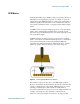
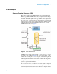
STM schematic is shown in Figure 3.
Figure 3 Basic STM schematic
STM can image a sample surface in either constant current or constant
height mode, as described in Figure 4. In constant height mode, the tip
remains in a constant plane above the sample, and the tunneling current
varies depending on topography and local surface properties. The
tunneling current measured at each location constitutes the image. The
sample surface, however, must be relatively smooth in order for the
system to acquire useful information.
In constant current mode, a feedback loop is used to adjust the height of
the tip in order to hold the tunneling current at a setpoint value. The
scanner height measured at each location is then used to map the surface