
User`s guide


Preparing for Imaging 4
Agilent 5500 SPM User’s Guide 60
voltages to opposite piezo elements in the scanner so that one element
elongates and the other contracts.
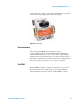
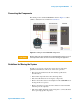
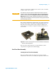
The scanner mounting fixture supplied with your system is designed to
keep the scanner and its components safe during handling (Figure 32).
The main cutout safely holds the scanner, while the smaller cutout
safely holds a nose assembly. A magnetic disk keeps additional tools
close at hand.
Figure 32 Scanner mounting fixture with nose assembly and spring key;
scanner in mounting fixture
The next sections will describe how to safely handle the scanner
components for long life and excellent imaging.
One-Piece Nose Assembly
Inserting the One-Piece Nose Assembly
The nose assembly is held in the scanner by an O-ring around its
circumference. To insert a nose assembly, first place the scanner in the
CAUTION
The thickness of the piezo elements determines how much they will
expand or contract per applied unit voltage. They are necessarily thin to
provide scanning resolution. If dropped, the scanner’s piezo elements
WILL break. Cracked or broken piezoelectrodes will result in abnormal
imaging. Proper handling is essential to preserve the long expected life of
your multi-purpose scanner.