
User`s guide

Preparing for Imaging 4
Agilent 5500 SPM User’s Guide 70
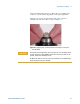
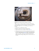
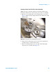
Figure 44 Move the lever to open the nose assembly disk.
4 Place the probe under the copper-colored spring clip on the nose
assembly disk. Use the alignment guides in the fixture to help locate
the probe laterally.
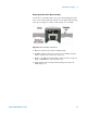
5 A small alignment spot on the fixture (Figure 43 on page 69)
indicates the proper location for the cantilever tip. Place the probe
such that the tip is close as possible to this spot.
6 Move the lever to the left to close the nose assembly disk.
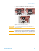
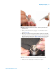
7 Use the tweezers to finely adjust the probe such that the cantilever is
aligned over the alignment spot. Only grasp the probe from the sides
to avoid damaging the cantilever.
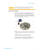
8 Grasping the nose assembly disk from the edges, remove it from the
fixture and align it on the nose assembly body already in the scanner.
Inserting the Scanner and Connecting Cables
At this point you should have the probe, nose assembly and scanner all
assembled into one unit.
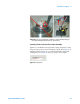
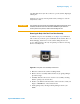
1 Make sure there is adequate clearance below the scanner socket in
the middle of the microscope.
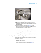
2 Place the scanner assembly into the scanner socket, with the
scanner’s frosted screen facing up and forward (Figure 45).