
User`s guide

Preparing for Imaging 4
Agilent 5500 SPM User’s Guide 80
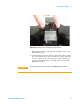
microscope base. You can install the detector into the scanner before or
after installing the scanner in the microscope base.
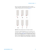
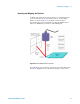
Figure 55 Inserting the detector module into the scanner
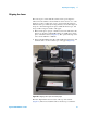
The Gain Switches on the detector determine whether the laser signal
is amplified before going to the rest of the electronics. Up (away
from the adjustment wheels) means no amplification, down means
the signal is amplified. Each switch represents one of the four
quadrants in the photodetector. All switches should be either up for
normal operation, or down to increase the signal for poorly reflective
cantilevers.
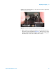
Detector alignment is completed through the PicoView software:
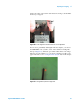
1 Launch PicoView. The Laser Alignment window (as well as other
windows) will open, displaying the position of the laser spot on the
photodiode detector (Figure 56). You can also click the Laser
Alignment toolbar button to open the window. The meter to the right
shows the Sum of all four quadrants. The Deflection signal is the
difference between the top and bottom halves divided by the Sum.