
User`s guide
Contact Mode Imaging 5
Agilent 5500 SPM User’s Guide 93
Setting Up for Contact Mode Imaging
Contact Mode imaging can be completed with any of the multi-purpose
scanners, using most any AFM probe and nose assembly. Contact Mode
tips, however, are designed specifically for this application, with lower
resonance frequency, softer cantilevers.
Constant Force Mode
In Constant Force Mode, a feedback loop between the Head Electronics
Box (HEB) and the controller maintains a constant deflection of the tip
based on the specified Setpoint voltage. The error signal, which is the
difference, measured in volts by the photodetector, between the Setpoint
and actual cantilever deflection, is read as the Deflection.
To begin imaging, follow the steps you learned in Chapter 4:
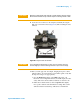
1 Insert the nose assembly into the scanner.
2 Insert a probe into the nose assembly.
3 Place the scanner in the microscope and connect its cables.
4 Align the laser on the cantilever.
5 Insert and align the detector.
6 Prepare the sample and mount the sample plate.
Then:
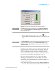
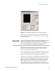
7 In the PicoView software choose Mode > Contact.
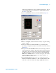
8 Choose Controls > CameraView to open the CameraView video
window.
9 Press the Close switch on the HEB to raise the sample until the tip is
close to, but not touching, the sample.
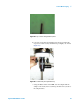
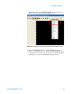
10 Viewing the video window, bring the tip and sample very close to
contact:
a Adjust the focus and x-y alignment of the video system such that
the tip is in sharp focus (Figure 64).