
User`s guide

Contact Mode Imaging 5
Agilent 5500 SPM User’s Guide 96
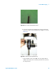
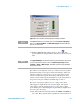
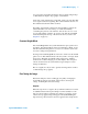
Figure 67 Servo window showing Setpoint voltage and Gains
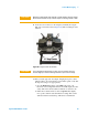
13 Click the Approach button in PicoView’s toolbar . The
system will raise the sample until the deflection reaches the Setpoint
value.
The indicator on the right side of the servo window shows the possible
displacement range for the Z piezo actuator. The indicator will be red
when the scanner is too far from (or too close to) the surface for the
system to maintain the Setpoint. The indicator will turn green when
contact is made and the Setpoint is maintained. A yellow bar will show
the position of the piezo within its available range of motion.
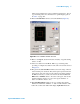
The center of the range is defined as “zero,” with positive values
indicating piezo displacement away from the sample, and negative
values being toward the sample. In Figure 67, the positive voltage
shows that the piezo is maintaining the setpoint while it is slightly above
the center point of its range.
14 Also in the Servo window make sure that the I Gain and P Gain are
set to 10 %. These gains dictate how quickly the system will react to
NOTE
If the Servo window is not already open, choose Controls >Imaging to
open it. The Scan and Motor and Real Time Images windows will also
open at the same time.
NOTE
The Approach Range, the distance that the system will move the scanner
to try to contact the surface, is set in the Microscope Setup window
(Controls > Setup > Microscope). A smaller approach range will make
the approach faster.