
User`s guide

Contact Mode Imaging 5
Agilent 5500 SPM User’s Guide 99
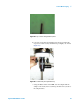
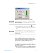
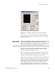
Figure 70 Scan and Motor window after scan has been initiated
As the tip moves across the first scan line, the system will adjust the
voltage on the z-piezo actuator to maintain constant force (as specified
by the Setpoint value).
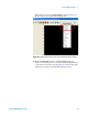
For each pixel, the system will record and plot the error signal (the
difference in volts between the surface-induced deflection and the
Setpoint) as the Deflection Image (in volts).
The correction signal (the voltage that the feedback loop applies to the
z-piezo to maintain the deflection at the Setpoint) is scaled by the piezo
sensitivity (nm/V) and plotted as Topography (in nanometers).
As the tip passes over regions of varying friction it will twist in the scan
direction as well as deflecting in the vertical axis. The detector senses
change in the cantilever‘s twisting motion and outputs it as the lateral
deflection (Friction) signal, which is plotted as the Friction image (in
volts). Changes in lateral force on the tip can be caused either by
changes in frictional properties across the sample or by variations in
topography. The Friction signal will therefore be a convolution of these
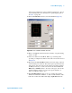
NOTE
The important parameter is the difference between the Deflection setting
(shown on the HEB) before beginning the approach and the initial
Setpoint value. A Setpoint of +1 V could be too low if the initial Deflection
was -0.1 V but too high if the initial Deflection reading was -2 V.