User manual
Manuals
Brands
Agilent Technologies Manuals
Computer equipment
E6198B
111
112
113
114
115
116
117
118
119
120
Using Load Cards and Loads
5
E6198B Switch/Load Un
it User Manu
al
5-51
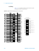
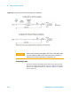
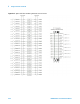
Load Wiring
Fig
ure
5-
37
is a sim
plif
ied schemati
c and P1 connector pinout
showing ho
w loads are connect
ed to P1.
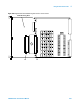
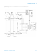
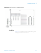
Figure 5-36
Agilent U7177A Connector J1 and Mating Connector P1
1
...
...
117
118
119
120
121
...
...
318