
User manual

Using Load Cards and Loads 5
E6198B Switch/Load Unit User Manual 5-59
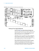
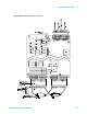
The Agilent E6178 Load Card comes with provisions for
user-installed flyback voltage protection. Figure 5-40 shows the
location for the flyback protection devices RV1 to RV8.
The flyback protection devices should be installed with the
positive side towards the UUT. On each of the 8 channels the
high (+) side should be located as shown in the component
locator diagram, Figure 5-40. MOV (Metal Oxide Varistor), or
back-to-back zener diodes are recommended for flyback voltage
protection.
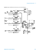
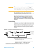
Protection Devices
Refer to Figure 5-41. Zener Diodes, MOVs (Metal-Oxide Varistor)
or Transzorbs
®
devices mounted at RV1 to RV8 provide current
path for the inductive load flyback. Select the protection device
so that it conducts at a voltage higher than the UUT's internal
protection. If the device's internal protection fails, then the
added external protection conducts to protect the UUT and the
load card.
Typical MOV (3mm) axial lead mounted specifications are:
Continuous DC voltage: 220 V
Transient energy
*
(10/1000mS): 0.90 Joules (watt-seconds)
Transient peak current
†
(8/20mS): 100 Amperes
CAUTION
The load cards are designed for a maximum of 500 V
peak
flyback
voltage. Operating the load cards without flyback protection
installed on the appropriate channels, or with flyback voltages in
excess of 500 V
peak
, may results in damage to the load card or SLU.
Figure 5-41 Typical Agilent E6178B Load Card Flyback Protection Circuit
* 10/1000mS refers to a standard pulse of 10mS rise and 1000mS to 50% decay of peak value.
† 8/20mS refers to a standard pulse of 8mS rise and 20mS to 50% decay of peak value.