
User manual

Using Load Cards and Loads 5
E6198B Switch/Load Unit User Manual 5-77
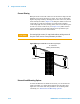
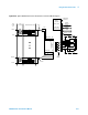
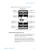
Figure 5-53 Agilent N9378 24-Channel Low-Resistance Load Card Block Diagram
Mother
Board
Interface
Relay Timer
Relay Slot
Decode Logic
P1
PB1
PB2
PB3
PB4
PS #1
PS # 2
PS #3
GPIB
J3
Configuration
Connector
External Mount Loads
NO1
NC1
Pwr1
Load
Switches
NO24
Pwr24
NC24
Chan1
Current
Sense &
Control
Address
Data
Power: +.5, ±12V
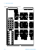
J9NC
J802-J807
J808 -J813
NO
2421
242
1
5A
fuses
Pwr1
User-installed
jumpers
UUT
Loads
P2
Chan24
Pwr24
Load1.1
Load1.2
Load1.3
Load1.4
Load24.1
Load24.2
Load24.3
Load24.4