
User manual

Using Load Cards and Loads 5
E6198B Switch/Load Unit User Manual 5-79
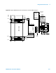
Selecting a Power Supply Configuration
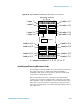
Each channel connects to the power bus via a Form C SPDT
(single-pole, double-throw) relay. This relay has a NO
(normally-open) and a NC (normally-closed) terminal. Each NO
terminal is connected to a pin on
J808–J813, and each NC terminal is connected to a pin on
J802–J807. Each pin on J802–J813 can be connected to any of
the four power busses on J801 via jumper wires (Figure 5-54).
The terminal block jumpering allows convenient pull-up or
pull-down of the various inputs. It also lets you terminate a UUT
load at a different voltage than ground.
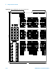
The factory default is to provide two jumper combs, one that
ties all the pins on J802–J807 together and one that ties all the
pins on J808–J813 together. The NO pins are also jumpered to
power bus 2, and the NC pins are jumpered to power bus 1. You
can easily cut the combs for J802–J807 and J808–J813 to
provide bus or pin isolation between the various input/power
bus connections.
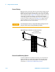
Using the Power Switches as General Purpose Relays
As with the E6177A and N9379A load cards, the N9378A
24-channel load card lets you use the load switching relay as a
general-purpose switching relay. The Common line (PwrX
where X is the channel number) on the input is brought back
out to the input, allowing each channel to operate in a
general-purpose (GP) configuration. This lets you, for example,
switch in an external power supply while bypassing the power
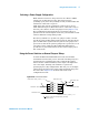
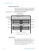
bus of the SLU. Figure 5-55 shows details of the load
configuration circuit.
Figure 5-55 Load circuit details
Node name: Chanx
Node name: Pwrx
Node names: Loadx.y, where y = 1-4 Node name: Pwrx
Node names: Comx.y, where y = 1-4
NC
NO
Node name: NCx
Node name: NOx
"Phantom" switch for switchpath editor (bus load)
x = Channel number