
User manual

6-22 E6198B Switch/Load Unit User Manual
6 Using the Pin Matrix Cards
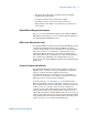
Reset State
The card resets to its default state whenever:
• Operating power is first applied
• Operating power is removed and then reapplied
• Bit 0 in the Control register (described in Appendix B) is
asserted
When the card is reset, all relay registers are cleared, column
disconnect relay control is set to automatic mode, and the relay
timer is started.
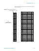
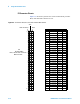
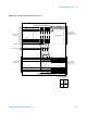
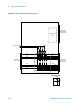
User Connectors and Pinouts
The figures and tables on the following pages shows the pinouts
for the Agilent E8782A and E8783A user connectors.
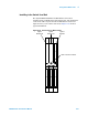
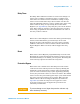
Figure 6-14 Column Disconnect and Bypass Protection Relays
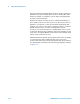
WARNING
SHOCK HAZARD. Only service-trained personnel who are aware
of the hazards involved should install, remove, or configure the
Switch/Load Unit or plug-in cards. Before you remove any
installed card, disconnect AC power from the mainframe and from
other cards that may be connected to the cards
CAUTION
STATIC ELECTRICITY. Static electricity is a major cause of
component failure. To prevent damage to electrical components,
observe anti-static techniques whenever removing a card from the
Switch/Load Unit or whenever working on a card.