
User manual


4-2 E6198B Switch/Load Unit User Manual
4 Configuring the Switch/Load Unit
Card Location Recommendations
This section describes the factory default card installation
locations. By adopting these installation defaults, consistency
from system to system is maintained. As well, locations are
reserved for future expansion if required.
For a single Agilent E6198B Switch/Load Unit installed in the
system
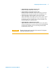
· Install matrix cards first. Slots 15 through 21 are reserved for
the matrix and custom modules. Starting from slot 21 and
working down, install matrix modules and custom modules in
the following order:
• Agilent Pin Matrix and Instrument Multiplexer Card
(E8792A or E8782A)
• Agilent Pin Matrix Card(s) (E8793A and/or E8783A)
• Agilent E8794A Custom Card(s)
Install the load cards using the following rules:
• Agilent N9379A 48-Channel Load Cards
Install any N9379A cards first, starting at slot #1.
• Agilent E6177A 24-Channel Load Cards
Install any E6177A cards next.
• Agilent U7177A 24-Channel Load Cards with current sense
Install any U7177A cards next.
• Agilent N9378A 24-Channel Load Cards
Install any N9378A cards next. To allow for future expansion,
leave an open slot after the last N9378A card.
WARNING
SHOCK HAZARD. Only service-trained personnel who are aware
of the hazards involved should install, remove, or configure the
Switch/Load Unit or plug-in cards. Before you remove any
installed card, disconnect AC power from the mainframe and from
other cards that may be connected to the cards.
CAUTION
STATIC ELECTRICITY. Static electricity is a major cause of
component failure. To prevent damage to electrical components,
observe anti-static techniques whenever installing or removing a
card in the Switch/Load Unit or whenever working on a card.