Agilent E6474A Mobile Voice MOS Test (VMT) Application Getting Started Guide Agilent Technologies
Notices © Agilent Technologies, Inc. 2007 Warranty No part of this manual may be reproduced in any form or by any means (including electronic storage and retrieval or translation into a foreign language) without prior agreement and written consent from Agilent Technologies, Inc. as governed by United States and international copyright laws. The material contained in this document is provided “as is,” and is subject to being changed, without notice, in future editions.
Introduction The Agilent Drive- Test solution is designed to allow benchmarking and qualification of voice quality over a cellular network. The measurement system consists of one set of equipment in the central office (CO) to process data for uplink measurement, and a second set of equipment in a mobile unit for processing downlink measurement. The information in this guide contains important information about setting up the system to run measurements.
• Phone specific cables. • E6473B- 882 - Nokia POP port to sound module cable. • E6473B- 883 - 2.5mm jack- plug to sound module cable. NOTE: PCs are supplied for the client-side of the system Minimum PC Specifications Refer to the Agilent E6474A User’s Guide (E6474- 90090) for details on the minimum and recommended PC specifications. Setup and Operation Overview The setup and operation of the measurement system may differ slightly for each usage scenario.
Contents Introduction 1 3 Setting Up Setting up the hardware 8 Setting up the Central Office (CO) equipment Setting up the Mobile van equipment 9 10 Setting up the software and license key (Central Office) 12 Installing the VQT and Office applications at the Central Office Setting up the VQT license keys 14 Re-installing PCI card drivers 17 2 Setting up the software and license key (Mobile Van) 21 Installing the VQT applications at the Mobile Van Setting up the USB Audio Module 26 21 Measuri
Contents 6 Agilent Mobile Voice MOS Test Application Getting Started Guide
1 Setting Up Setting up the hardware 8 Setting up the Central Office (CO) equipment 9 Setting up the Mobile van equipment 10 Setting up the software and license key (Central Office) 12 Setting up the software and license key (Mobile Van) 21 This chapter covers the setup of the hardware and software in the Agilent Mobile Voice MOS Test Software system.
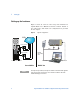
1 Setting Up Setting up the hardware Figure 1 shows an overview of the setup of the hardware for Agilent Mobile Voice MOS Test Software solution. Details of the central office and mobile van configuration are provided in this chapter.
Setting Up 1 Setting up the Central Office (CO) equipment Up to four channels can be linked for each control PC in the central office. To set up the equipment in the central office: 1 Connect CO equipment’s analog port to POTs with a RJ- 11 cable. NO TE Only analog phone line should be used. The equipment does not work with digital telephone lines. Write down the phone number of the each line. 2 Connect an RJ- 14 to RJ11 splitter to each of the two ports on the rear of the office equipment.
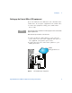
1 Setting Up Setting up the Mobile van equipment To set up the equipment in the mobile van: 1 Install and configure your USB Audio Module. Refer to manufacturers instructions for more information. 2 Connect the phone ear- port to the Analog In, Channel 1 of the USB Audio Module. 3 Connect the phone microphone- port to the Analog Out, Channel 1 of the USB Audio Module. 4 Connect the phone trace- port to your laptop.
Setting Up 1 USB Audio Module Headphone & Optical Out Analog In Analog Out 4 3 2 Microphone 1 4 3 2 1 Ear USB Connection Mobile Laptop Data/Trace Connections Figure 3 Typical one-phone mobile van configuration Agilent Mobile Voice MOS Test Application Getting Started Guide 11
1 Setting Up Setting up the software and license key (Central Office) The central office software has already been installed and pre- configured. By default the system is supplied with the following Windows® login and password: Login: agilent Password: agilent The following procedure may be used if the software has to be re- installed. Contact your local Agilent sales representative if you have any problems with the installation.
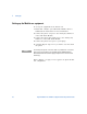
Setting Up 3 Step through the installation screens until you see the option for Mobile or Office installation The following installation dialog appears (see below). 4 Select Office to Install Voice Quality Test (VQT) software Edition 4.5 Follow the installation instructions.
1 Setting Up Setting up the VQT license keys NO TE An Ethernet connection to the equipment is required before you can enter the 10/100 Ethernet license. Follow these steps: 1 Start the Voice MOS Test application. The Server Setup dialog box appears. Figure 4 Server Setup dialog box 2 In the Server 1 Selection list, select Local. 3 Select the Single Server Testing check box. 4 Under Server 1 - Acquisition Hardware, select 10/100. 5 Click START Client/Server Connections.
Setting Up 1 You are prompted to save your configuration. Select Yes and enter a configuration name (Figure 5). Figure 5 Unsaved Scenario Dialog After you have saved the configuration the Enable 10/100 Ethernet Test Interface(s) dialog box appears (Figure 6). Figure 6 Enable 10/100 Ethernet Test Interface(s) dialog box 6 Enter the 10/100 license key and click OK.
1 Setting Up 7 When the Success dialog appears, select Continue (Figure 7). Figure 7 10/100 License Success Dialog 8 In the PSQM, PAMS and PESQ Authorization keys dialog, select Enter Keys (Figure 8). Figure 8 PSQM, PAMS and PESQ Authorization keys dialog 9 In the Enable Features dialog, select the Enable PESQ Clarity Measurement option.
Setting Up 1 The PESQ Key Entry dialog box appears (Figure 9). Figure 9 Enabling ITU standard PESQ measurement 10 Enter the PESQ key and then click OK. Figure 10 PESQ Key Entry dialog box 11 Click OK to close the Enable Features dialog box. 12 Exit the VQT application and proceed to the next stage of the installation. Re-installing PCI card drivers Your office PC is supplied with a fully configured and working PCI audio card.
1 Setting Up 1 If new hardware is detected, the new hardware wizard starts. 2 Follow the wizard instructions. 3 When the wizard asks for a driver location for the installation, select “No, not this time”. Refer to Figure 11.
Setting Up 1 4 Select next and then select “Install from a list or specific location (Advanced)”. Refer to Figure 12.
1 Setting Up 5 Choose the following location to install the driver from; C:\WINDWOS\system32. The driver should already be on your system. Refer to Figure 13. Figure 13 Enter driver location 6 Follow the installation wizard until the driver for the audio PCI card has been detected and installed. 7 You may be asked to re- boot your PC. 8 After installation, check your PC system hardware configuration to verify the driver and audio PCI card have been installed and detected.
Setting Up 1 Setting up the software and license key (Mobile Van) You need to install the software and set up the license key for both the client PC in the mobile van. Each PC requires a separate copy of the Mobile VQT Software. NO TE The 10/100 licenses is not used by the mobile van configuration. However, the license still needs to be enabled as it is an integral part of the VQT application, which is the same application used on the server (CO) side of the network.
1 22 Setting Up 3 Select the Mobile installation option. 4 Follow the installation instructions. Use the default directories The following installation dialog appears (see below).
Setting Up 1 Setting up the VQT license keys Follow these steps: 1 Start the VQT application. Figure 14 Server Setup dialog box 2 In the Server 1 Selection list, select Local. 3 Select the Single Server Testing check box. 4 Under Server 1 - Acquisition Hardware, select 10/100. 5 Click START Client/Server Connections.
1 Setting Up You are prompted to save your configuration. Select Yes and enter a configuration name. Figure 15 Unsaved Scenario Dialog After you have saved the configuration the Enable 10/100 Ethernet Test Interface(s) dialog box appears. Figure 16 Enable 10/100 Ethernet Test Interface(s) dialog box 6 Enter the 10/100 license key and click OK.
Setting Up 1 7 When the Success dialog appears, select Continue. Figure 17 10/100 License Success Dialog 8 In the PSQM, PAMS and PESQ Authorization keys dialog, select Enter Keys. Figure 18 PSQM, PAMS and PESQ Authorization keys dialog 9 In the Enable Features dialog, select the Enable PESQ Clarity Measurement option.
1 Setting Up The PESQ Key Entry dialog box appears. Figure 19 Enabling ITU standard PESQ measurement 10 Enter the PESQ key and then click OK. Figure 20 PESQ Key Entry dialog box 11 Click OK to close the Enable Features dialog box. 12 Exit the VQT application. Setting up the USB Audio Module NO TE Before setting up your USB Audio Module, follow the manufacturers instructions for installing device drivers and configuring the hardware.
Setting Up 1 Follow these steps: 1 Open the ASIO- USB Control Panel. Select Start > All Programs > Agilent Wireless Solutions > E6474A > Utilities > ASIO USB Control Panel.
1 Setting Up • System Performance: Relaxed Figure 22 ASIO USB Control - ASIO tab options 4 Select the Control Tab and set as follows (refer to Figure 23 on page 28): • Mute all channel Monitor. • Input and Output: Set as required. The left slider controls channels 1 and 3. The right slider controls channels 2 and 4.
2 Measuring Voice Quality Part 1: Voice MOS Test (VMT) Office Utility 30 Part 2: Preparing Central Office for measurements 31 Part 3: Using Mobile Van and E6474A Sequencer for measurements 35 Part 4: Measurement results 38 The measurement of mobile network voice quality makes use of two separate sets of equipment. • Mobile van equipment. • Central Office (CO) equipment.
2 Measuring Voice Quality Part 1: Voice MOS Test (VMT) Office Utility The VMT Office Utility allows you to configure parameters or start testing at central office (server) part of the system. To start the utility, select Start > All Programs > Agilent VQT > Voice MOS Office Test Utility.
Measuring Voice Quality 2 Part 2: Preparing Central Office for measurements Figure 25 Agilent VMT sample uplink parameters 1 Start Agilent VMT. 2 Activate the desired test channel by selecting its corresponding check box. NO TE When a the Channel LED is green then the telephony line is connected. When the Channel LED is red then the telephony line is unplugged or faulty. When the Channel LED flashes green then telephony line is connected and a call is in progress. 3 Select the reference speech file.
2 Measuring Voice Quality 5 Enter a time- out period sufficient to cover the number of defined iterations. Generally this is approximately 20 seconds per iteration. NO TE Each iteration will consist of a pair of downlink and uplink data point. The estimated test time for each iteration is approximately one minute. It is highly recommended that you use the default 20 secs time-out between each measurement. This will allow the system to recover from dropped call.
Measuring Voice Quality 2 9 At any point of time, or upon completion of measurement, clicking STOP TEST will terminate measurement and generate MOS results. How to enable auto-run after a reboot The Voice MOS Test Office Utility may be configured as a startup program when your Windows operating systems starts and logs in. If measurements are to be made automatically after a reboot of your PC, the operating system needs to have the auto- login enabled.
2 Measuring Voice Quality Figure 28 Set password requirement c When prompted, type the default password “agilent” that is be used for auto- logon. Figure 29 NO TE 34 Confirm password To revert to the normal Windows logon procedure, enable the “user must enter a user name and password to use this computer”.
Measuring Voice Quality 2 Part 3: Using Mobile Van and E6474A Sequencer for measurements 1 Run the Agilent E6474A application. (Refer to the E6474A User’s Guide and online help for more information). 2 After configuring your hardware add the phone device to your sequence in the sequencer system panel. 3 Add a parallel sequence node (refer to Figure 30).
2 Measuring Voice Quality • Call Control Test - Call Initiator (refer to Figure 32) a Auto Dial = YES b Immediate Dial = YES c Continuous Call = NO d Call Duration = 200 or above It is recommended to establish a call with the minimum 200 seconds when running the Voice MOS Test. This allows several MOS to be collected and obtain meaningful measurement results for each call session.
Measuring Voice Quality 2 b Auto Answer = Yes c Channel - select the channel for the USB audio device d Set the other properties for the Voice MOS Test according to your network and test requirements. Figure 33 Call Control Properties - Receiver 5 In the Sequencer window, activate the desired test channel by selecting its corresponding check box, in accordance with the USB Audio Module configuration.
2 Measuring Voice Quality Part 4: Measurement results Downlink MOS results can be found on the mobile van PC, while uplink MOS results on the CO control PC. At the end of measurement, MOS results for each channel will be displayed in the E6474A application. Recorded speech samples and VQT log files are archived in the work directory that was defined in the test properties in the E6474A application. Downlink MOS results are stored in the recorded data file in the E6474A application.
Measuring Voice Quality Figure 35 2 Chart View example Agilent Mobile Voice MOS Test Application Getting Started Guide 39
2 40 Measuring Voice Quality Agilent Mobile Voice MOS Test Application Getting Started Guide
3 Troubleshooting This chapter consists of frequently asked questions and contact information. Frequently Asked Questions Why is the VQT program not launching? Ensure the default directories are used during the installation process. Can customized speech file be used to perform measurement? No, it cannot. The supplied collection of speech is recommended for the ITU standard PESQ algorithm. The collection of male and female speech is a good representation of various phonemes in different languages.
3 Troubleshooting Why is the equipment in the central office not picking up calls? The call may be from a digital phone. Some offices use digital phones. The equipment only supports analog phone lines. However the equipment can be connected to a digital ISDN phone line as long an ISDN- to- analog converter is used. Why is the file, mos_score.txt, not available after data collection? You may have used space characters when naming some of the folders in the work directory.
3 Troubleshooting 6 Click: File and choose Enable Features 7 Check: Enable PESQ and enter ten digit key code 8 Exit Could not locate E6474A Voice MOS Test Office Utility. You may have installed the Mobile application on your Central Office desktop. Please go to Add/Remove Programs and delete following programs: • Agilent E6474A- X Voice Mos Test • Agilent VQT 4.
3 Troubleshooting Continuous Synchronization Time-out error when I start Voice MOS testing The Maya 44 USB device needs to be properly configured before starting Voice MOS test. After installing Maya 44 USB audio device, you must initialize ASIO Control Panel and properly configure the USB Tab, ASIO Tab, and Controls Tab. To open ASIO Control Panel go to: Start > Programs > Agilent Wireless Solutions > Utilities > ASIO Control Panel.
Troubleshooting 3 Before starting the voice quality test, please make sure that E6474A Voice MOS Test Office Utility is loaded and in a ready state (The button in the lower middle must say “Stop Test”). Also, it is good practice to empty CH1 through to CH4 directories prior the voice MOS test. This way only the current test data is stored in the directory. Interference between the Maya device and phones may introduce undesirable noise on internal audio processing.
3 Troubleshooting Contact Information For technical support, contact your local country- specific Agilent office and they will quickly forward your enquiry to the person who can best help you solve your problem. For up- to- date, country- specific contact information, go to http://www.agilent.com/find/contactus.
A Appendix A- Calibration of USB Audio Module Measurement may normally be performed at the recommended settings for the ASIO USB control application, refer to “Setting up the USB Audio Module” on page 26. However, attenuation or boosting of voice amplitude may occur along the communication network (which includes the mobile handset), such that undesirable low SNR (signal- to- noise- ratio) or clipping occurs.
A Appendix A- Calibration of USB Audio Module The Server Setup dialog box appears. Figure 36 Check if USB Audio Module calibration is necessary 3 In the Server 1 Selection list, select Local. 4 Select the Single Server Testing check box. 5 Under Server 1 - Acquisition Hardware, select 10/100. 6 Click START Client/Server Connections. 7 Click Start in the right panel of the window. (See Figure 37.
Appendix A- Calibration of USB Audio Module A For good results, test (measured) waveform’s peak is normally within 4 dB of the reference waveform’s peak.
A Appendix A- Calibration of USB Audio Module 8 If the test waveform is outside the 4 dB range adjust the Input and Output Control sliders on the ASIO USB Control Panel. See Figure 38 on page 50. Figure 38 ASIO USB Control Panel adjustments Adjust sliders to improve MOS values Both the ear and microphone need to be calibrated. The ear calibration affects the downlink quality (mobile side of the system). The microphone calibration affects the uplink quality (central office side of the system).
Index Numerics P 10/100 license key, 15, 24 PESQ key entry, 17, 26 phone support, 46 PSQM, PAMS, PESQ license key, 16, 25 A acquisition hardware 10/100, 14, 23 S C server setup, 14 setting up hardware central office, 9 mobile equipment, 10 setting up license keys, 12, 21 setting up the hardware, 8 setting up USB Audio Module, 26 support contact, 46 Can customized speech file be used to perform measurement, 41 central office set up, 9 central office sub-system, 31 contact information, 46 E enabling
Index 52 Agilent Mobile Voice MOS Test Application Getting Started Guide