
User`s guide


GPS Connections for E74xx Systems B
Agilent E6474A User’s Guide 165
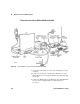
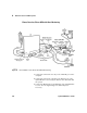
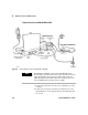
4 Connect the GPS RS-232 port of the Agilent E645x receiver to
the GPS RS-232 port of the adapter box, using the RS-232
cable.
5 Connect the MDT port of the adapter box to the MDT/RTCM
port of the Trimble Placer GPS 455 unit, using the RS-232
straight-through cable.
6 Connect the digital port of the adapter box to the Digital IO
port of the Trimble Placer GPS 455 unit, using the RS-232
cable.
7 Connect the Heading Sensor to the Heading Sensor port of
the Trimble Placer GPS 455 through the female 9-pin
connector on the DR sensor cable supplied by Trimble. (See
Figure 64 on page 164.) The connector labeled Heading
Sensor connects to the heading sensor; the connector labeled
Sensors connects to the Placer GPS 455. (See Figure 64 on
page 164.)
8 Connect the GPS antenna to the GPS ANT port of the Trimble
Placer GPS 455 unit. Agilent Technologies recommends that
a “bulkhead mount” GPS antenna be used whenever possible
for improved performance.
9 If equipped, connect the phone interface cable to the phone.
Connect the opposite end to an unoccupied port of the Dual
Serial Port PCMCIA card.
10 Connect the power cables to the Trimble Placer GPS 455, the
Agilent E645x receiver, and the computer. Connect the
lighter plug for each device to the 4-to-1 lighter socket
adapter.