
Technical data


38 Getting Started Guide
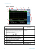
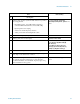
2 Front Panel Features
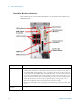
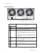
Rear-Panel Features
Item
Description
# Name
1 Line power input The AC power connection. See the product specifications for more details.
2 FAN Fan speed control (settings are HIGH and AUTO).
3 INHIBIT Inhibit switch. The settings are DEF (default) and MAN (manual).
• When the switch is in the default position, the chassis is powered up by
the front panel ON/Standby pushbutton. This is the recommended
setting.
• When the switch is in the manual position, the chassis is powered up by
the Inhibit input signal on the rear panel INHIBIT/VOLTAGE MON
DB-9 connector.
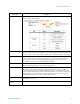
4 INHIBIT/
VOLTAGE
MON
This DB-9 connector provides access for testing of internal power supply
voltages. The voltages (by Pin #) are: (1) Logic Gnd, (2) +5 VDC, (3)
Rsrvd, (4) +3.3 VDC, (5) Inhibit [Low], (6) +12 VDC, (7) Rsrvd,
(8) -12 VDC, (9) Logic Gnd.
510 MHz REF
OUT
This BNC connector provides an output of the test set’s internal 10 MHz
frequency reference signal. It is used to lock the frequency reference of
other test equipment to the test set.
6 10 MHz REF IN This BNC connector accepts an external 10 MHz frequency reference
signal. It is used to lock the test set to the frequency reference of other test
equipment.