
Technical data


50 Getting Started Guide
2 Front and Rear Panel Features
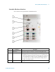
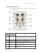
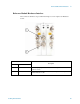
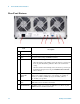
Rear-Panel Features
Item
Description
# Name
1 Line power input The AC power connection. See the product specifications for more details.
2 FAN Fan speed control (settings are HIGH and AUTO).
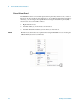
3 INHIBIT Inhibit switch. The settings are DEF (default) and MAN (manual).
• When the switch is in the default position, the chassis is powered up by
the front panel ON/Standby pushbutton. This is the recommended
setting.
• When the switch is in the manual position, the chassis is powered up by
the Inhibit input signal on the rear panel INHIBIT/VOLTAGE MON
DB-9 connector.
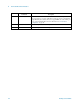
4 INHIBIT/
VOLTAGE
MON
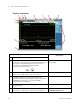
This DB-9 connector provides access for testing of internal power supply
voltages. The voltages (by Pin #) are: (1) Logic Gnd, (2) +5 VDC, (3)
Rsrvd, (4) +3.3 VDC, (5) Inhibit [Low], (6) +12 VDC, (7) Rsrvd,
(8) -12 VDC, (9) Logic Gnd.
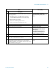
510 MHz REF
OUT
This BNC connector is not used by the E6640A test set. The front panel 10
MHz OUT connector should be used instead.
6 10 MHz REF IN This BNC connector is not used by the E6640A test set. The front panel
REF IN connector should be used instead.