
User`s guide


22 E6651A User’s Guide
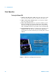
2 Getting Started
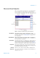
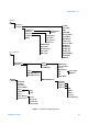
Setting Window
This window contains detailed information about the mode
of operation and parameter settings.
Figure 5 Setting Window Configuration
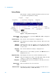
Measurement
Mode
The current mode of operation (BSE, SA or SG) is displayed
in this window.
Center Frequency The current center frequency is displayed here.
Link Direction The Link Direction display always indicates “UL” in SA and
BSE mode.
ADC Input
Saturation
Saturation may cause the signals to become distorted. When
this condition occurs, the SAT Indicator is illuminated in one
of four colors.
Attenuator
Setting
The current Attenuator Setting is displayed here.
Error When an error occurs during operation, the ERR Indicator is
illuminated in red.
Amplitude Setting This displays the Test Set's current transmitter power.
RF Output This area displays the status of the RF output. When the RF
output is on, this area is highlighted in green.
Editing Title The Editing Title shows the parameter currently selected to
be modified.
Measurement
mode
This area indicates the selected mode.
Reference Clock The Reference Clock selection is displayed in this area as
either INT (Internal) or EXT (External).
E6655A Lab
App Status