
Technical data

124 Chapter 4
Two Port Insertion Loss
Measuring Two Port Insertion Loss
Two Port Insertion Loss
Measuring Two Port Insertion Loss
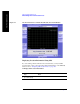
This test measures the loss of a cable or other device over a specified frequency
range.
Insertion loss measurements are important in accurately quantifying the amount of
loss a signal will incur as it passes through a cable, attenuator, or any other device.
In S-parameter terms, insertion loss is referred to as an S
21
measurement. “S” stands
for scattering.
NOTE Any cable added to your measurement configuration will add some loss that must be
accounted for. For example, a jumper cable placed between the test set and the
antenna feedline (or other device) you are connecting will add some loss to the
measurement.
If you add a jumper cable to your measurement configuration, you must normalize
out the loss associated with the cable at your current measurement frequency.
Otherwise, your measurement results will be inaccurate, and you will probably
adjust transmit parameters in error.
Insertion loss measurements have a variety of uses. However, the example
procedures focus on two kinds of two-port insertion loss measurements that you
need as preparation for other test set measurements:
• Measuring the 3 meter (10 ft) test cable, 60 cm (2 ft) normalization cable, and
high power attenuator provides values you can store as RF In Loss and RF Out
Loss.
— RF In Loss is used with the Spectrum Analyzer, Channel Scanner,
cdma Analyzer, cdma2000 analyzer, 1x-EVDO Analyzer, and the
GSM Analyzer.
— RF Out Loss is used with the Signal Generator.
— RF Out Loss is the measured loss of cables and other devices between the
E7495A/B RF Out (Port 1) and the receiver under test.
• Measuring the high power attenuator and 60 cm (2 ft) normalization cable
provides stored Power Meter Loss (PM loss), which is needed for using the
Power Meter.
— PM loss is the measured loss of cables and other devices between the signal
source and the power sensor.