
Technical data


Chapter 4 135
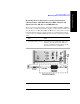
Two Port Insertion Loss
Measuring Two Port Insertion Loss
Two Port Insertion Loss
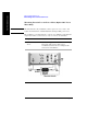
Determining The Lowest (Worst) Insertion Loss and Its
Frequency
2 [Level/Location] If the insertion loss trace is not visible, you can
change the reference level or use Autoscale to have
the test set select a reference level for you.
• Press [Autoscale] to display the trace so that it
fills the screen from top to bottom.
• Press [Ref Level] and then enter the
appropriate value and press [dB] to manually
select a level for the trace.
• Press [Scale/Div] and then enter the
appropriate value and press [dB] to manually
select the number of dBs per line on the
graticule.
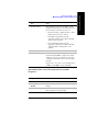
3 [Store As]
4 [Store As PM Loss] Saves the loss for use with the power
measurement. This PM Loss figure only remains
valid for as long as you continue to use the same
“characterized assembly”, that is, the same cables
and pads.
If Option 600 - Power Meter is not installed, [Store
as PM Loss] and [PM Loss] are unavailable.
Step Notes
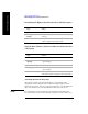
1[Marker]
2 On [Type] select
Normal.
Each time you press this softkey, the selected option
changes.
3 [Marker to Peak] Places a marker on the highest peak. The marker
value is displayed in the upper right.
Step Notes