
Technical data

182 Chapter 7
CDMA Analyzer
Using the CDMA Analyzer
CDMA Analyzer
Using the CDMA Analyzer
CDMA transmitter measurements verify proper transmitter performance and are
typically made with the base station out of service. Important metrics are:
• frequency error
• PN and time offsets
• channel power
• waveform quality (estimated Rho)
• carrier feedthrough
• noise floor
• pilot channel power
• page channel delta power from pilot
• sync channel delta power from pilot
• quick changing channel delta power from pilot
• For information about CDMA over air measurements, refer to “CDMA Over
Air” on page 219.
CAUTION The maximum power for the RF In (Port 1) and RF Out/SWR (Port 2) ports is
+20 dBm (100 mW). When using the 8481A/8482A or N8481A/N8482A with
Option CFT Power Sensors, the maximum input power applied to the Power Sensor
is +24 dBm (300 mW). When using the 8481D Power Sensor, the maximum input
power is +20 dBm (100 mW). When directly coupled to a base station (BTS) or
Access Network (AN), the test set can be damaged by excessive power applied to
any of these three ports.
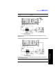
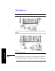
To prevent damage in most situations when you directly couple the test set to a base
station, use the high power attenuator between the test set and the BTS.
Common CDMA Tx Analyzer Measurements
Preparing to Make CDMA Tx Analyzer Measurements
The first step in measuring CDMA transmitter performance is to take the base
station out of service. The next step is to choose the type of time reference available.
The measurement configuration depends upon the type of time reference you choose
to use. Optimally, a GPS time reference is desired. GPS provides an independent
time reference that can help determine if the base station under test is synchronized
with the rest of the network. Base stations not synchronized with the rest of the
network are referred to as “island cells”.