
Technical data

Chapter 7 211
CDMA Analyzer
Optional CDMA Tx Analyzer Measurement Settings
CDMA Analyzer
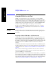
external attenuator/cabling. When you set the RF Generator to –113 dBm (with the
RF OUT Loss field turned
On and the external attenuator/cabling loss value entered)
the output at the end of the RF test cabling is –113 dBm.
Example: If you want to set the signal generator to –113 dBm, the attenuator and RF
cabling measures 42.51 dB (measured with the 2 port insertion loss measurement
screen prior to this test), the RF OUT Loss field is turned
On (with the 42.51 dB loss
value entered). The actual RF output of the signal generator is –70.49 dBm, the
attenuator and RF cabling attenuated the signal to the desired level; so the RF signal
at the end of the test cable/attenuator is –113 dBm. This also points out the
importance of accurately measuring the loss of the attenuator and connecting cables.