
Technical data

278 Chapter 10
Distance to Fault
Measuring Distance to Fault
Distance to Fault
Measuring Distance to Fault
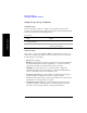
A signal is transmitted from the RF Out/SWR port of the test set to the
cable-under-test. The signals reflected from faults in the cable are received by the
test set.
In performing this measurement, the test set uses frequency domain reflectometry.
The changing interference of the transmitted and reflected signals contains
information about the distance to one or more faults. This information can be used to
find the physical distance to the faults. The distance displayed on the test set is the
physical distance to the probable faults, corrected for the cable loss and velocity
propagation factor of the cable.
Measured Distance - the Effects of Frequency and Points
It is not always obvious how frequency range affects measured distance and
resolution, and it often appears to be counter-intuitive. If you are new to making
Distance to Fault measurements, this section will help clarify what is happening.
In the following equations
• The Speed of Light (‘c’) is a constant value of 3 * 10 to the power 8 meters per
second.
• Your test cable’s transmission speed (relative to light) is V
Rel
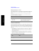
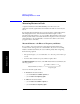
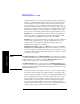
The Measured Distance (in meters) of the DTF measurement is determined by the
following equation:
You can see from this equation that:
•To
increase the measured distance:
— you can
increase the number of points, or
— you can
reduce the frequency span.
•To
reduce the measured distance:
— you can
reduce the number of points, or
— you can
increase the frequency span.
Measured Distance (in meters)
1
4
---
Number of Points× c× V
Rel
×
Frequency Span
---------------------------------------------------------------------------------=