
Technical data

Chapter 11 301
E1 Analyzer
Making E1 Measurements
E1 Analyzer
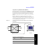
• Line Code: Configures the test set to transmit and expect to receive a line code
that is compatible with the network’s design. There are two types of line coding
used in E1 networks:
— AMI - Alternate Mark Inversion is a traditional line code.
— HDB3 - High Density Bipolar 3 replaces runs of 4 zeroes with a special code
that is not compatible with AMI. It allows greater flexibility of data patterns
by enhancing repeater synchronization by increasing pulse density, thereby
providing greater throughput.
• Framing: Configures the test set to transmit and expect to receive a particular
framing pattern that is compatible with the network’s design. It enables the test
set to receive the E1 signal and to then synchronize, identify, and extract the
individual channels.
— Unframed - Causes the test set to simulate a loss of frame condition.
— PCM30 - A framing format consisting of 30 traffic channels, 1 slot reserved
for the frame alignment signal (FAS) and 1 slot reserved for common
channel signaling.
— PCM30 + CRC4 - A framing format consisting of 30 traffic channels, 1 slot
reserved for the frame alignment signal (FAS) with CRC and 1 slot reserved
for common channel signaling.
— PCM31 - A framing format consisting of 30 traffic channels, 1 slot reserved
for the frame alignment signal (FAS)
— PCM31 +CRC4 - A framing format consisting of 30 traffic channels, 1 slot
reserved for the frame alignment signal (FAS) with CRC
• Pattern: Configures the test set to expect a particular test pattern. Many test
patterns are available to 'stress' the circuit in a particular manner or to gain
maximum insight into a particular problem.
• Tx Pattern: Allows you to select either Normal or Inverted patterns.
• Tx Clock: Configures the test set to use one of the following methods to derive
the transmit clock frequency.
— Internal - The transmit clock is derived within the test set and is
independent of the incoming signal. This is useful when the device or line
under test is configured to synchronize on the incoming signal. In this case
the return clock frequency of the return signal should match the transmit
clock frequency of the test set.
— Primary Rx - The transmit clock frequency is derived from the signal