
Technical data


308 Chapter 11
E1 Analyzer
Making E1 Measurements
E1 Analyzer
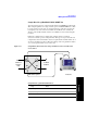
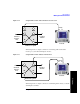
Sample Monitor Full E1 Test
This example shows how to monitor an E1 circuit without disrupting service.
During this test the source of signal from the far end can be either live data or
pattern data from a second test set. This mode is very similar to End-to-End Hard
Loop mode, with the exception that the signal present on the Primary Tx jack is a
buffered replica of the signal present on the Primary Rx jack. When monitor jacks
are not available, this feature allows the technician to break into a live E1 and pass
that signal through the test set, thereby keeping the circuit in-service. This is useful
for monitoring long-term statistics of an E1 circuit.
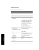
22 Setup results display.
a. [Results]
b. Use up and down
buttons to select.
c. [Select]
Displays a list of results information that can be
displayed in the Results pane. Make a selection
based on the need of the application. [Control]
enables several soft keys on the right that control
choices specific to each test mode.
23 Setup to inject an error.
a. [Control]
b. [Alarm/Error]
c. Use the Up and
Down arrow
buttons to select.
d. [Select]
e. [Inject]
Allows you to select and then inject the alarm or
error you want to test. Causes the error or
condition that is currently displayed on the Inject
button to occur. Note that some selections cause a
single event to occur while others maintain a
constant state. The text on the button changes to
reflect the appropriate action.
Press the [Inject] menu key to toggle between
On
and
Off. Selecting On will inject the error selected
with the [Alarm/Error] menu key during Step
23(b).
Step Notes