
Technical data

Chapter 11 313
E1 Analyzer
Making E1 Measurements
E1 Analyzer
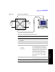
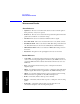
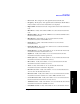
Figure 11-4 Delay Connection Diagram
To Preform a Sample Delay Mode Test Procedure
OUT
OUT
IN IN
To Base
Station
From
Channel
Service
Unit
Primary
Rx Tx
DSX Service panel
Test Set
Step Notes
1 [Mode]
2 [Backhaul]
3 [E1 Analyzer]
4 [Get Started/ Test Mode]
5 Perform Delay test.
a. [Delay]
b. [Full E1]
Use this test mode to measure the delay
between the Primary Tx and Rx ports.
Use this measured delay to determine the
approximate distance between near end
and far end. The far end of the line must
be manually looped during this test.
Since a signal is being sent on the E1
line, service on the E1 will be affected.
Delay measurements require full E1
bandwidth.
6 [Setup] Select this to display a list of setup
choices that pertain to this test mode.