
Technical data


Chapter 11 321
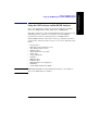
E1 Analyzer
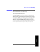
Measurement Results
E1 Analyzer
screen on the test set.
Testing and Fault Mitigation
The complexity of E1 testing certainly parallels or possibly exceeds that of RF tests
at a cell site. Shadowing efforts and customer expression have shown that most cell
site technicians reduce the complexities of backhaul E1 testing down into a series of
well-defined steps. These tests are often not comprehensive but are often sufficient
to determine the continuity of an E1 circuit with a high degree of confidence. Often
times the test sequence is developed by an experienced technician and is determined
by finding the shortest path to an adequate measurement on a particular piece of
readily available equipment. E1 testing often involves one technician on each end of
a circuit. In the case of wireless, the technician at the switch end, very experienced
at backhaul testing, is often working with a field technician that has a broader-based
set of knowledge and is often less experienced in backhaul testing. The switch
technician quickly develops a test procedure that involves the least amount of verbal
instructions with the field technician.
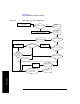
E1 Facility Summary
This next section describes the elements in a typical E1 backhaul facility. Based on
this information, typical fault conditions and what procedures are typically followed
to restore service to the E1 span.
With almost no exception all circuits leased from the TELCO are routed through at
least one central office facility. If this were not the case, planning and managing the
repeaters needed for E1 transmission would be an onerous task.
Isolating Faults Using Test Equipment
Test equipment can be used to generate and monitor alarms and errors. Test
equipment is connected to the E1 facility in a variety of ways. BNC jacks are often
available on the equipment. When the plug is inserted into the jack the circuit is
interrupted. Sometimes a monitor jack is available. When a plug is inserted into the
monitor jack the circuit is not interrupted and a -20 dB signal is available at the jack.
When none of these is available the signal may be monitored at a connection block,
sometimes referred to as a “punch-down block”. The table below, “E1 Facility
Access Methods,” describes the three typical access methods.
E1 Facility Access Methods