
Technical data

330 Chapter 12
GSM and EDGE Analyzer
Using the GSM Analyzer and the EDGE Analyzer
GSM and EDGE Analyzer
Three different graphical views of your measurements are available. You can view:
• Channel Scanner
• Power versus Time
•Spectrum
The measurements conform to the following GSM standards:
•GSM 450
•GSM 480
•GSM 850
•GSM 900
• DCS 1800
• PCS 1900
CAUTION The maximum power for the RF In (Port 1) and RF Out/SWR (Port 2) ports is
+20 dBm (100 mW). When using the 8481A/8482A or N8481A/N8482A with
Option CFT Power Sensors, the maximum input power applied to the Power Sensor
is +24 dBm (300 mW). When using the 8481D Power Sensor, the maximum input
power is +20 dBm (100 mW). When directly coupled to a base station (BTS) or
Access Network (AN), the test set can be damaged by excessive power applied to
any of these three ports.
To prevent damage in most situations when you directly couple the test set to a base
station, use the high power attenuator between the test set and the BTS.
NOTE To prevent unusual display information from being shown, ensure that you have
selected a valid GSM Standard. It is possible for you to set a Chan Std that allows
you to enter a lower Stop channel number than the current Start channel number
resulting in unexpected information in the display. This is because some of the
channel standards have discontinuities and reversals in channel numbers.
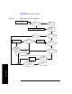
Performing a Basic GSM or EDGE Transmitter Measurement
The first step in measuring GSM or EDGE transmitter performance is to take the
base station out of service or, for an in-service measurement, connect the test set to
the coupled port. You must also know the channel or frequency of the EDGE signal
to be analyzed.