
Technical data

414 Chapter 16
Spectrum Analyzer
Using the Spectrum Analyzer
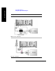
Spectrum Analyzer
Using the Spectrum Analyzer
Use the Spectrum Analyzer in direct connect mode to:
• Verify that your transmitted signal does not interfere (produce spurs and
harmonics) with other signals.
• Verify spectral integrity—look at a signal to see if it meets expectations, look for
unwanted signals.
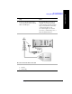
Use the Spectrum Analyzer in Over Air mode to:
• Look for interference generated by other transmitters that can interfere with your
transmit band.
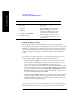
CAUTION The maximum power for the RF In (Port 1) and RF Out/SWR (Port 2) ports is
+20 dBm (100 mW). When using the 8481A/8482A or N8481A/N8482A with
Option CFT Power Sensors, the maximum input power applied to the Power Sensor
is +24 dBm (300 mW). When using the 8481D Power Sensor, the maximum input
power is +20 dBm (100 mW). When directly coupled to a base station (BTS) or
Access Network (AN), the test set can be damaged by excessive power applied to
any of these three ports.
To prevent damage in most situations when you directly couple the test set to a base
station, use the high power attenuator between the test set and the BTS.
NOTE The RF In loss can be added manually, or automatically by performing an insertion
loss measurement. For measurement instructions refer to “Performing (and
Calibrating) a Basic One Port Insertion Loss measurement” on page 47 or
“Normalizing and Performing a Basic Two Port Insertion Loss Measurement” on
page 125.