
Technical data


Chapter 16 421
Spectrum Analyzer
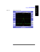
Using the Spectrum Analyzer
Spectrum Analyzer
Setting Up the Signal Generator
“Setting the Range Control” on page 418
You can set up the signal generator while in the Spectrum Analyzer mode from the
Setup menu. For more detailed information on the signal generator setup and
operation, refer to “Using the Signal Generator” on page 402.
CAUTION The maximum power for the RF In (Port 1) and RF Out/SWR (Port 2) ports is
+20 dBm (100 mW). When using the 8481A/8482A or N8481A/N8482A with
Option CFT Power Sensors, the maximum input power applied to the Power Sensor
is +24 dBm (300 mW). When using the 8481D Power Sensor, the maximum input
power is +20 dBm (100 mW). When directly coupled to a base station (BTS) or
Access Network (AN), the test set can be damaged by excessive power applied to
any of these three ports.
To prevent damage in most situations when you directly couple the test set to a base
station, use the high power attenuator between the test set and the BTS.
NOTE The lowest level the signal generator can go to is –90 dBm. In order to get a lower
level, you must use an external attenuator. You can compensate for the attenuator in
the RF Out Loss.
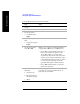
Step Notes
1[Setup]
2 [Sig Gen]
3[Freq/Chan]
4 Enter the channel number or
the frequency using the
numeric keypad.
5 • For channel select [Rev]
or [Fwd]
• For frequency select
[GHz], [MHz], [kHz], or
[Hz],