
Technical data

Chapter 17 463
Basic System Operations
Setting System References
Basic System Operations
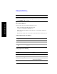
NOTE A frequency/time reference indicator in the lower-right of the screen shows both the
selected reference and its status.
Reference indicators include: “GPS,” “Int Ref,” “Even Sec,” “Ext 10 MHz,” “Ext
13 MHz,” or “Ext 19.66 MHz.”
Status indicators include:
• Green dot to indicate that the reference is locked
• Yellow triangle to indicate that the reference is acquiring lock
• Red X to indicate that the reference is not locked
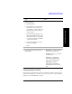
Setting up the DC Bias Option
The DC Bias Tee, Option 300 - DC Bias, provides power from the Agilent E7495B
to the amplifier at the top of a base station tower, or the end of the cable run. The DC
voltage (12 volts) is output on the center conductor of Port 1, RF Out. The option
enables you to test with the amplifier powered on. DC bias defaults to off when you
select a new measurement type which does not depend on either Port 1 or Port 2,
and it must be turned on each time you want to use it. It stays on as long as you’re
using measurements that use RF In or Out. DC Bias cannot be saved in the On
position as a state and is turned off when the power is cycled, including when going
into the sleep state. If you do not have the option, it is grayed out on the screen.
NOTE The maximum current draw is 800 milliamps.
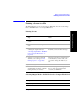
3 [Fr/Time Ref] Displays additional menu buttons. With Internal
GPS and External Even Sec, both frequency and
time references are active. This is used when
measuring CDMA signals to get valid PN
offsets.
With the other five options, you get only
frequency.
4 Select the frequency/timing
reference you want.
Step Notes