
Technical data


Chapter 18 501
T1 Analyzer
Making T1 Measurements
T1 Analyzer
11 Setup Tx clock.
a. [Tx Clock]
b. [Internal]
This is the default selection after test set preset
and covers the situation when a hard loop is
configured at the far end. If a separate test set
is used at each end then the test set on one end
should have the Tx Clock set to Primary Rx
(assuming the incoming signal is connected to
this jack.) Another alternative is to use a
second T1 circuit connected to the Secondary
Rx jack to establish proper timing.
12 Setup the Tx LBO.
a. [Tx LBO]
b. [0 dB]
This is a typical level found at the customer
demarcation point.
13 Setup the loop code.
a. [Loop Code]
b. [In-band]
Your choice depends on the far end CSU
configuration.
14 Setup the slip reference.
a. [Slip Ref]
b. [None]
Disables the frame slip measurement.
15 Setup the second Tx.
a. [Second Tx]
b. [AIS]
Use the default condition.
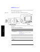
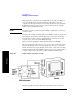
16 Setup the display.
a. [Display]
b. [Status]
c. [Pri]
Enables the [Display] options on the buttons on
the right. Activates only the Primary Status
pane. The inactive channel should be
deactivated to cease the display of invalid
measurements.
17 Setup the alarms.
a. [Alarms]
b. [Pri]
This selection causes the Alarm pane to toggle
between Primary and Secondary. Use this
selection to observe the Primary Results in the
Alarm Panel.
Step Notes