
Technical data

Chapter 3 61
1xEV-DO Analyzer and Over Air Test
Making 1xEV-DO Tx Measurements
1xEV-DO Analyzer and Over Air
Test
Making 1xEV-DO Tx Measurements
• “Common 1xEVDO Tx Analyzer Measurements” on page 61
• “Preparing to Make 1xEVDO Tx Analyzer Measurements” on page 61
• “Performing a Basic 1xEVDO Transmitter Measurement” on page 63
1xEV-DO transmitter measurements verify proper transmitter performance and are
typically made with the access network (AN) still in service. The Access Network
only needs to be taken out of service when you are setting or measuring the Tx
Power Out level, and this is typically only performed during Installation,
Optimization, and Preventative Maintenance.
Important metrics for both Tx and Over the Air measurements include:
• Frequency Error
• PN and Time Offsets
• Non Idle Power
•Idle On/Off Ratio
• Pilot + MAC power
• Pilot Rho (estimated)
• MAC Rho (estimated)
CAUTION The maximum power for the RF In (Port 1) and RF Out/SWR (Port 2) ports is
+20 dBm (100 mW). When using the 8481A/8482A or N8481A/N8482A with
Option CFT Power Sensors, the maximum input power applied to the Power Sensor
is +24 dBm (300 mW). When using the 8481D Power Sensor, the maximum input
power is +20 dBm (100 mW). When directly coupled to a base station (BTS) or
Access Network (AN), the test set can be damaged by excessive power applied to
any of these three ports.
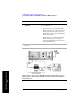
To prevent damage in most situations when you directly couple the test set to a base
station, use the high power attenuator between the test set and the BTS.
Common 1xEVDO Tx Analyzer Measurements
Preparing to Make 1xEVDO Tx Analyzer Measurements
When measuring 1xEVDO transmitter performance, there is no need to take the
access network out of service. The Access Network only needs to be taken out of
service when you are setting or measuring the Tx Power Out level, and this is