
Technical data

Chapter 3 83
1xEV-DO Analyzer and Over Air Test
Optional 1xEV-DO Tx and Over Air Analyzer Measurement Settings
1xEV-DO Analyzer and Over Air
Test
(dB) or absolute power (dBm). The test set defaults to relative. The top graticule
(horizontal line) represents the total power in the 1xEV-DO channel. The scale per
division is set to 5 dB per division by default, but you can change it if you wish.
If the reference level is set to relative, the reference level represents the total power
in the 1xEV-DO channel, and is displayed as 0.0 dB. If the reference level is set to
absolute, the reference level displays the actual power (in dBm) for the particular
time domain section relevant to the selected CDP type. For example, in pilot CDP
mode, the absolute power level is measured only over the pilot burst region of the
signal.
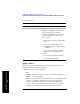
To Set the 1xEV-DO Transmitter Reference Level:
NOTE The insertion loss of the test cable and high power attenuator must be accounted for
to obtain accurate 1xEV-DO power measurements such as Pilot+MAC power. The
insertion loss of the test cable/attenuator combination is accounted for as the RF In
Loss, which is an offset applied by the test set to the power measurements.
Setting Measurement Time
The measurement time setting allows you to alter the speed at which measurements
Step Notes
1. [Level]
2. On [Reference] select
Abs or
Rel.
Each time you press this softkey, the selected
option changes.
3. [RF IN Loss]
4. Enter the RF In Loss using
the numeric keypad.
If you are using a cable and attenuator
connected to the access network power
amplifier, enter the combined cable and
attenuator loss here. The RF In Loss can be
obtained by measuring the Insertion Loss. See
“Two Port Insertion Loss” on page 123.
Note: If data had been previously entered in
[RF IN Loss], that data will be lost and
replaced by the value you enter here.
5. [dB]