
Installation guide

ParBERT Overview Getting Started
Agilent 81250 ParBERT Installation Guide, February 2002 17
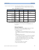
Clock Modules Every ParBERT system requires one master clock module which
generates the system clock and synchronizes all data generator and
analyzer channels of the system.
One clock module can supply its clock to up to 11 data
generator/analyzer modules. The combination of a clock module and its
attached data modules is called a clockgroup. Clockgroup #1 is present
in every ParBERT system.
The master clock module can also control up to two slave clock
modules. Slave clock modules are needed if a system consists of more
than 11 data generator/analyzer modules. This leads to the clockgroups
#2 and #3.
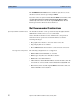
A deskew probe can be connected and the Agilent 81200 Trigger Pod can
be attached to the master clock module.
The deskew probe is used for compensating for internal signal delays.
The trigger input pod allows to control test execution by applying
external signals.
Supported are the E4805B and the E4808A clock modules. The latter is
required for ParBERT 43G systems (see also ”ParBERT 43G
Components” on page 58) and systems containing 3.35 Gbit/s modules.
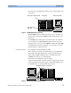
Figure 7 E4805B Clock Module
It is also possible to install two or more master clock modules in one
mainframe. This results in mutually independent ParBERT systems
which share only the housing.