
Installation guide


ParBERT Overview Getting Started
Agilent 81250 ParBERT Installation Guide, February 2002 21
The ParBERT Approach
It has been mentioned that a single Agilent 81250 system can comprise
up to three clock modules in a master-slave configuration. Such a
configuration uses expander frames and has up to three clockgroups or
up to 33 data generator/analyzer modules.
It has also been mentioned that one mainframe can house several Agilent
81250 systems. They consist of independent clock modules with
associated data generator/analyzer modules. Such configurations make it
possible to test a device under asynchronous conditions using
independent clock pulses.
The concept of the Agilent 81250 Parallel Bit Error Ratio Tester is to
create so-called virtual systems from the system’s present hardware
resources (clock modules, data modules, generator and analyzer
frontends).
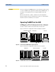
Virtual Systems
The basic (default) system is called DSRA (DSR = digital stimulus and
response, system A).
If the hardware comprises several independent clock modules—not
connected as slaves—then additional systems are available. By default,
they get ascending names, such as DSRB, DSRC, and so on.
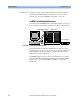
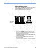
Figure 9 Virtual Systems in One Mainframe
Separate systems are widely used for testing multiplexers or
demultiplexers. Such devices generally require different clock
frequencies at the generating and analyzing sides. MUX/DEMUX tests
can be performed by one system, if the ratio of these frequencies is 2
n
,
such as 2, 4, 8, 16, and so on. If it is not, separate data generating and data
analyzing systems will do the job.
DSRCDSRA DSRB
Clock modules