
Instruction manual


176 Chapter 6
Replacement Procedure
A20 Digital Motherboard Replacement
A20 Digital Motherboard Replacement
Tools Required
• TORX screwdriver, T10, T15, and T20
Removal Procedure
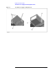
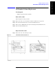
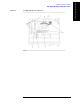
Refer to Figure 6-8 for this procedure.
Step 1. Remove the mouse, the external keyboard and the parallel printer cable if they are
connected to the rear panel.
Step 2. Remove the outer cover as described in “Outer Cover Removal” on page 166.
Step 3. Remove the following assemblies.
• A25 Handler I/O board (refer to “A25 Handler I/O Board Replacement” on page 175.)
• A21 PCI DSP CARD/A24 GPIB Card assembly (refer to “A21 PCI DSP Card / A24
GPIB Card Replacement” on page 185.)
Step 4. Disconnect the following cables.
• Connected to the Front Panel (touch screen, opt. 016) (item 1)
• Connected to the A32 USB connector (item 2)
• Connected to the A10 Analog Mother Board (item 3).
• Connected to the A28 FDD (item 4).
• Connected to the A27 HDD (item 6)
• Connected to the Front Panel (display) (item 5)
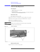
NOTE The mylar cable (item 5) and its connector are very fragile. It’s recommended to replace
the mylar cable when the cable is disconnected and connected frequently.
Step 5. Remove six TORX T10 screws (item 7) fastening the digital motherboard.
Step 6. Lift the digital motherboard.
Replacement Procedure
Step 1. Reverse the order of the removal procedure.