
Instruction manual

Chapter 6 189
Replacement Procedure
A52 Inverter Board Replacement
6. Replacement Procedure
A52 Inverter Board Replacement
Tools Required
• TORX screwdriver, T8, T10, T15, and T20
• Flat edge screwdriver
Removal Procedure
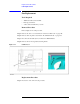
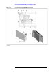
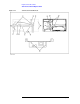
Refer to Figure 6-15 for this procedure.
Step 1. Remove the front panel as described in“Front Panel Removal” on page 167.
Step 2. Release the clamped cables from the clamps (item 1) on the cover.
Step 3. Disconnect the cables (item 4, 5).
NOTE Keep the mylar cable (item 6) connected.
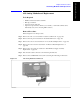
Step 4. Disconnect the cables (item 2, 3, and 7) from the touch screen controller if the option 016 is
installed.
Step 5. Remove the four TORX T10 screws (item 8) fastening the cover to the front panel.
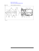
Step 6. Disconnect the cable of connector for the cable (item 7).
NOTE The connector for the cable (item 7) is not connected in the E5061A/E5062A without the
option 016.
Step 7. Disconnect the cables (item 9,10).
Step 8. Remove the two TORX T15 screws (item 11) fastening the inverter assembly.
Step 9. Remove the two TORX T8 screws (item 12) fastening the inverter to the bracket.
Replacement Procedure
Step 1. Fasten the new A52 Inverter board to the bracket.
Step 2. Reverse the order of the removal procedure.