
Instruction manual


196 Chapter 7
Post-Repair Procedures
Post-Repair Procedures
Post-Repair Procedures
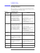
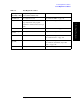
Table 7-1 Post Repair Procedures lists the required procedures that must be performed
after the replacement of an assembly. These are the recommended minimum procedures to
ensure that the replacement is successfully completed.
Table 7-1 Post-Repair Procedures
Replaced
Assembly or Part
Required Adjustments
Correction Constants (CC)
Verification
A1 Source Board
Perform the following required
adjustments using “Source Board” in
Spot Adjustment of the program.
Synthesizer Gain Adjustment
Local Output Power Adjustment
Source Output Power Adjustment
Receiver IF Range Adjustment
Receiver Ports Characteristics Adj.
“To Execute the Diagnostic Test” on page
101
Frequency Accuracy Test
RF Output Level Accuracy and Flatness Test
RF Output Level Linearity Test
Trace Noise Test
Crosstalk & System Dynamic Range Test
Dynamic Accuracy Test
Uncorrected System Performance Test
A2 Receiver Board Perform the following required
adjustments using “Receiver Board” in
Spot Adjustment of the program.
Frequency Reference Adjustment
Local Output Power Adjustment
Source Output Power Adjustment
Receiver IF Range Adjustment
Receiver Ports Characteristics Adj.
“To Execute the Diagnostic Test” on page
101
Frequency Accuracy Test
RF Output Level Accuracy and Flatness Test
RF Output Level Linearity Test
Trace Noise Test
Crosstalk & System Dynamic Range Test
Dynamic Accuracy Test
Uncorrected System Performance Test
A10 Analog
Motherboard
No adjustment needed Inspect the Booting Process
When the symptom of failure is out of
specification, perform the performance test.
A20 Digital
Motherboard
Set jumper and BIOS parameters on the
A20. For details, see “To configure the
A20 Digital Motherboard and BIOS” on
page 120.
Inspect the Booting Process
A21 PCI DSP Card Perform the following required
adjustments using “Analog Interface” in
Spot Adjustment of the program.
Writing ID
Inspect the Booting Process
“To Check the Front Panel” on page 109
“To Check the External Trigger Input” on
page 112
A22 Front Panel
Keyboard
No adjustment needed “To Check the Front Panel” on page 109
A25 Handler I/O
Board
No adjustment needed “To Execute the Diagnostic Test” on page
101